

IJI has been engaged with a major UK bank over the last 18 months helping them introduce new methods of working, and IBM’s Collaborative Lifecycle Management tooling to support these methods. Business Analysts now capture their requirements in Rational Requirements Composer (RRC), Solution Architects create their designs in Rational Software Architect (RSA) using the Unified Modelling Language (UML), Infrastructure & Security Architects add deployment topologies to the designs using RSA’s Deployment Planning extension, and everything is underpinned by Work Items and Source Control in Rational Team Concert (RTC).
This programme of change marks a major shift in the bank’s IT culture away from disparate production of Microsoft Word documents and Visio diagrams towards a supportable solution of collaborative, model-driven architecture and design. IJI has contributed to the specification of new practices, the creation and delivery of training material, guidance documentation in text and video form, the founding of a Community of Practice (CoE), advanced training and development programmes for Champions within the CoE, mentoring support for project teams adopting the new methods and tools, and customisation of the Rational toolset to deliver specific capabilities required by the IT teams.
One significant aspect of our engagement has been to roll out the Deployment Planning extension to RSA. This add-on delivers features for the design and specification of deployment infrastructure. The Unified Modelling Language (UML) already offers the deployment diagram as a means to show how software components execute upon middleware and hardware, plus the other elements that are required to deliver a fully working system. Critics argue that the UML deployment diagram offers little more than pictures, lacking a rich enough semantic for tool-based validation; furthermore there is insufficient information to enable useful integrations with industry-standard build and provisioning engines.
The Deployment Planning extension replaces the UML deployment diagram with a new modelling concept called a topology. Topologies are analogous with UML models in that they capture the elements of an infrastructure design, the relationships between elements, and views of the design via diagrams. To achieve this a different modelling language is used, the Topology Modelling Language (TML).
The method which underpins the use of TML requires that several topologies are created when considering deployment architectures for a system, with each topology refining the previous one and introducing ever greater levels of detail. The first is the Logical Topology and its role is two-fold:
- Understand the deployment context by adding TML elements to represent physical and logical Locations (e.g. data centres, security zones) within which Nodes sit that host the in-scope software Components.
- Ensure traceability with source UML models by creating TML equivalents of Components and Actors.
TML nodes are best thought of as placeholders for some stack of hardware and middleware. This stack may already exist or may still need to be specified and provisioned, but either way this is a level of detail that does not need to be considered while the deployment context is being determined. And to help determine the system context, actors may be included in the topology to maintain focus on scenarios of use.
An example logical topology is shown in the image below:
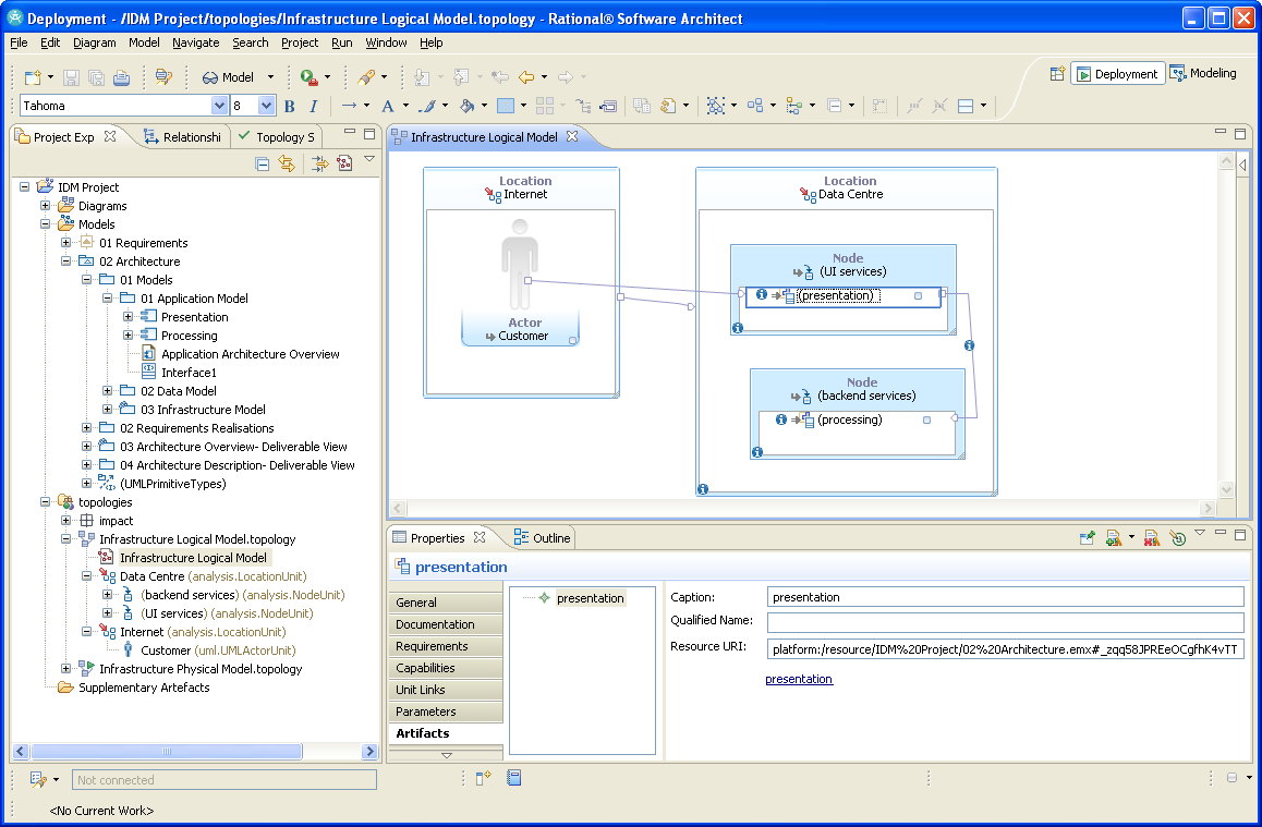
You can see two locations on the diagram, ‘Internet’ containing a primary actor and ‘Data Centre’ with two nodes hosting the components to be deployed. Each component is linked to its equivalent UML Component, and an example link is shown in the ‘Properties’ view.
Once the Logical Topology is sufficiently complete, a Physical Topology is created to refine the infrastructure design and begin specifying the technology which will be used for deployment:
- Nodes are realised with physical stacks of hardware, operating systems, databases, networking, and so on.
- Additional infrastructure is included as required to complete the system.
TML provides a feature whereby technology units may be labelled conceptual, meaning that the unit (e.g. an x86 server) is not fully defined and thus retains a certain level of abstraction; the benefit for system architects and designers is that a physical topology can be used to validate a deployment solution at a high level with a focus on performance, robustness, throughput and resiliency. Design details such as processor architectures, operating system versions, inter-process messaging solutions and the like should be deferred for now.
An example physical topology is shown in the image below:
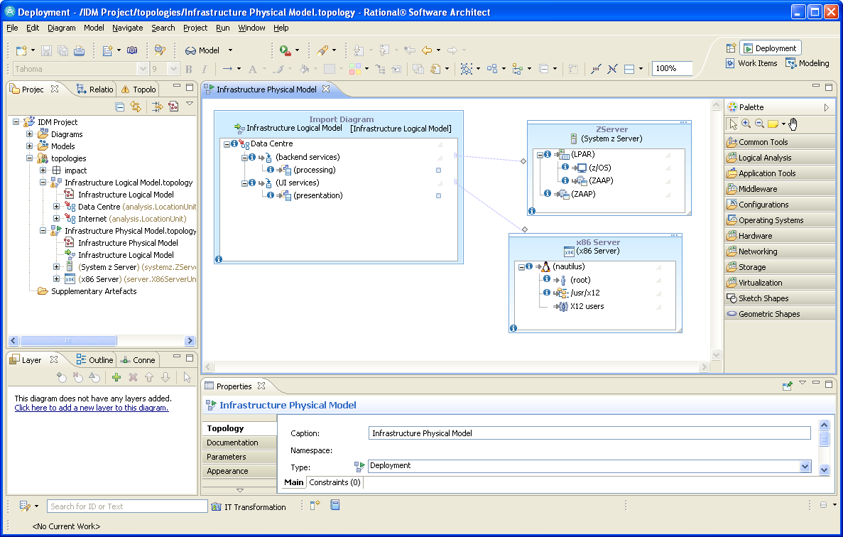
In RSA’s ‘Project Explorer’ on the left, you can see that we have a logical and physical topology. Traceability between the two is achieved via an Import Diagram, visible on the left of the diagramming pane. The import contains two nodes and each is realised by a specific stack of technology; each stack is conceptual, denoted by braces around the name.
The Physical Topology contains mainly conceptual units thus is not a complete design, therefore one or more Deployment Topologies is created to finalise the design:
- Conceptual units are realised with equivalent, non-conceptual units.
- Full details are added such as server names, IP addresses, patch versions, communication protocols, port numbers, etc.
At this level, a single conceptual server may be realised by several concrete servers to represent a load balancing or hot-standby infrastructure solution. Furthermore, a non-specific operating system must now be realised by a real solution, whether that be Windows or Red Hat Linux or whatever.
IJI was tasked with extending the Deployment Planning palette with new topology units that best represent the bank’s IT estate as well as strict constraints on the relationships which may exist between units. The resulting solution has enabled Architects to specify infrastructure and security designs much quicker and with greater quality than before, resulting in faster progress through internal governance and less re-work. Furthermore all the bank’s Architects are seeing huge benefits by working in a more collaborative fashion using Rational Software Architect and Collaborative Lifecycle Management.